Prevent Gas Buildup in Manifold CVD Machines: Expert Insights & Best Practices
Chemical Vapor Deposition (CVD) machines are critical equipment in semiconductor manufacturing, materials science, and advanced coating production. One of the most persistent operational challenges engineers face is gas buildup in manifold systems—a problem that can compromise product quality, reduce equipment efficiency, and create safety hazards. Understanding the mechanisms behind gas accumulation and implementing preventive strategies is essential for maintaining optimal CVD performance and supporting sustainable manufacturing practices.
Gas buildup occurs when reactive or inert gases fail to properly circulate through the manifold, creating pressure imbalances, thermal hotspots, and potential equipment damage. This issue not only affects production yields but also increases energy consumption and waste—factors that directly impact your facility’s sustainability goals. By addressing gas management proactively, manufacturers can reduce operational costs, minimize environmental impact, and extend equipment lifespan.
Understanding CVD Manifold Systems and Gas Dynamics
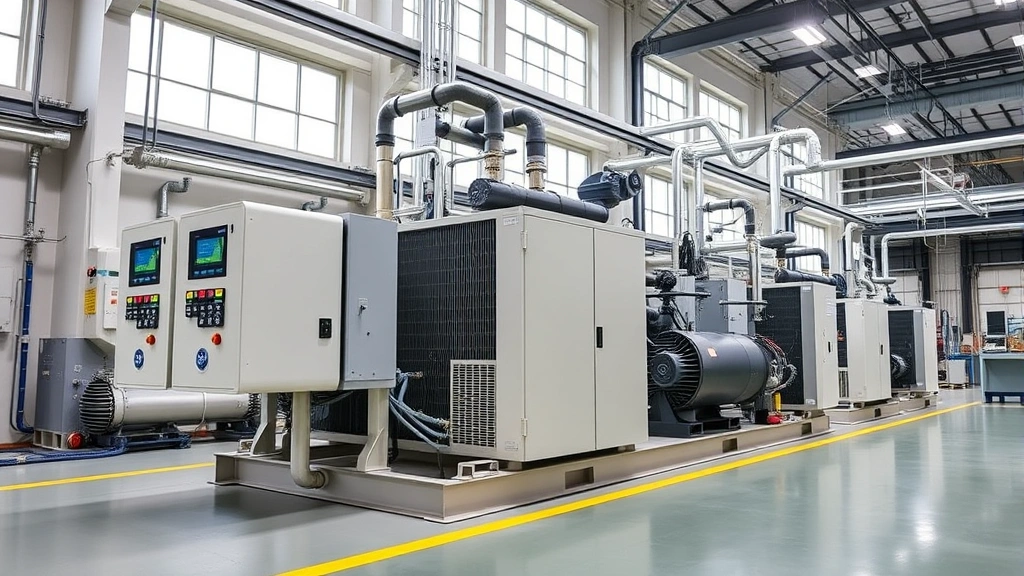
CVD manifold systems serve as the central hub for gas distribution in deposition chambers. These systems must precisely control gas flow rates, pressure levels, and temperature profiles to ensure uniform coating deposition. The manifold contains multiple inlet points, mixing chambers, and outlet ports designed to deliver precursor chemicals and carrier gases in exact proportions.
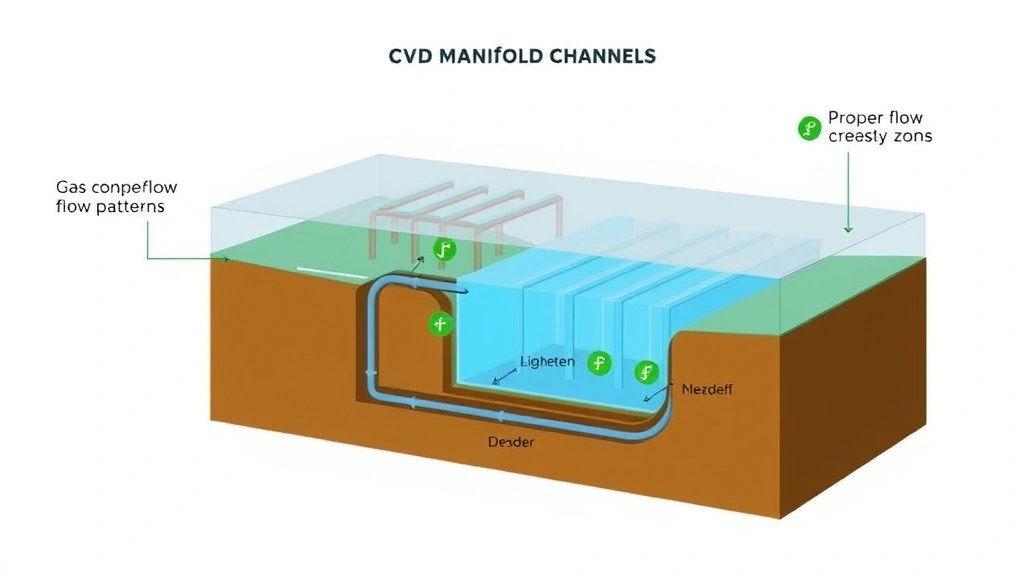
Gas dynamics within a manifold depend on several factors: inlet pressure, outlet pressure differential, gas molecular weight, temperature gradients, and pathway geometry. When these variables are not properly balanced, gases can become trapped in dead zones—areas where flow velocity drops below critical thresholds. Understanding these dynamics is fundamental to preventing accumulation and maintaining consistent deposition quality.
The primary gases used in CVD processes include silane, tungsten hexafluoride, titanium tetrachloride, and various carrier gases like nitrogen and argon. Each has distinct viscosity and density characteristics that affect flow behavior. Mixing incompatible gases or operating at incorrect pressure ratios can create stagnant pockets where gases accumulate, leading to unwanted chemical reactions and deposit formation within the manifold itself.
Proper manifold design incorporates smooth transitions, minimal dead leg sections, and optimized internal geometries to promote laminar or controlled turbulent flow. However, even well-designed systems require active management and monitoring to prevent gas buildup during extended operational cycles.
Root Causes of Gas Buildup in CVD Equipment
Pressure imbalances represent the primary cause of gas accumulation. When outlet pressure exceeds inlet pressure or when differential pressure drops below minimum thresholds, gases cannot be effectively evacuated. This often occurs during equipment startups, process transitions, or when vacuum pump performance degrades over time.
Thermal inconsistencies create secondary complications. Temperature variations within the manifold cause gas density changes, which can reverse flow direction in certain sections. Cold spots near manifold walls allow gases to condense, while hot zones may cause localized pressure spikes. These thermal gradients are particularly problematic in large-scale CVD systems processing high-temperature materials.
Contamination and particle accumulation obstruct gas pathways. Dust, corrosion products, or polymerized precursor materials gradually reduce effective channel diameters, increasing resistance to flow. As blockages develop, pressure rises upstream while flow rates decrease downstream, creating ideal conditions for gas stagnation.
Improper valve operation prevents effective gas isolation and evacuation. Stuck check valves, leaking isolation valves, or malfunctioning pressure regulators disrupt the carefully balanced gas distribution sequence. During purge cycles, if isolation valves fail to close completely, residual gases from previous runs mix with fresh gases, creating unpredictable flow patterns.
Manifold design flaws inherently limit performance. Older equipment or poorly engineered systems may contain excessive dead legs—sections of tubing with minimal flow where gases naturally accumulate. Sharp bends, undersized sections, and internal obstructions force gases into low-velocity regions where they cannot be evacuated efficiently.
Understanding these root causes enables targeted interventions. Rather than treating gas buildup as an inevitable consequence of CVD operation, systematic diagnosis and correction can virtually eliminate this problem while improving overall energy efficiency.
Pressure Management and Flow Control Solutions
Effective pressure management begins with precise measurement and control systems. Modern CVD equipment should incorporate multiple pressure sensors throughout the manifold—at inlet, outlet, and critical intermediate points. These sensors feed data to automated control systems that adjust inlet pressure, outlet vacuum, and gas flow rates in real-time.
Inlet pressure optimization ensures adequate driving force for gas circulation. Most CVD manifolds require inlet pressures between 0.5 and 5 bar, depending on precursor type and chamber design. Pressures below this range result in insufficient flow velocity and gas stagnation; pressures above it may cause turbulent mixing and unwanted side reactions. Pressure regulators with ±2% accuracy maintain optimal conditions throughout operational cycles.
Outlet vacuum control is equally critical. The pressure differential between inlet and outlet determines gas velocity through the manifold. Most systems operate with outlet pressures between 0.1 and 1 mbar. When vacuum pump performance degrades—a common issue in facilities running continuous processes—outlet pressure rises, eliminating the pressure differential needed for effective evacuation. Regular vacuum pump maintenance, including oil changes and seal inspections, prevents this degradation.
Mass flow controllers (MFCs) provide precise gas flow regulation at the inlet. Modern MFCs offer accuracy within 1-2% of setpoint and respond dynamically to changing manifold conditions. By programmatically adjusting flow rates during process sequences, operators can ensure continuous gas movement and prevent stagnation. MFC calibration should occur quarterly, as drift over time reduces control accuracy.
Purge gas protocols actively remove residual gases between process runs. Inert gas purging—typically using nitrogen or argon—sweeps through the entire manifold at elevated flow rates, dislodging trapped gases and preventing contamination carryover. Effective purge cycles require 5-10 manifold volume exchanges at flow rates 50% higher than normal operating conditions. Automated purge sequences triggered between recipe steps eliminate manual oversight and ensure consistency.
Backpressure regulation maintains consistent outlet pressure despite changing load conditions. Electronic backpressure regulators automatically adjust downstream restriction to maintain setpoint, compensating for vacuum pump performance variations and preventing the pressure collapse that allows gas accumulation.
Implementing these pressure and flow control measures requires investment in modern instrumentation, but the return on investment appears within months through improved yields, reduced scrap rates, and decreased energy consumption.
Preventive Maintenance Strategies
Scheduled maintenance prevents the degradation that leads to gas buildup. A comprehensive preventive maintenance program should include:
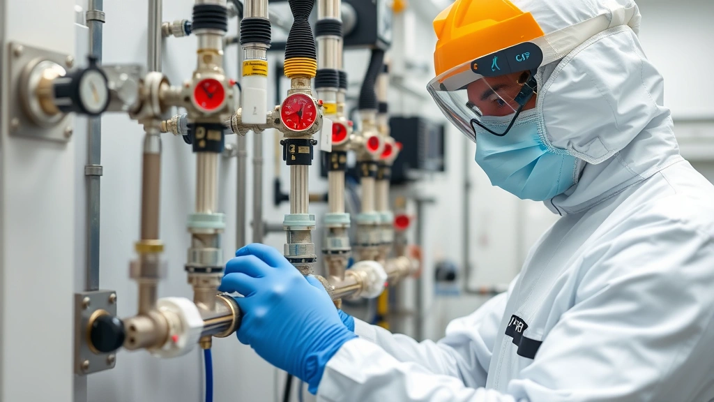
- Monthly inspections: Visual examination of manifold exteriors for corrosion, leaks, or physical damage. Check all visible fittings and connections for signs of gas leakage (soap bubble testing). Verify pressure gauge readings against known calibration standards.
- Quarterly cleaning: Flush the manifold with appropriate solvents to remove accumulated deposits. For systems processing silicon-based precursors, isopropanol or acetone effectively removes polymerized residues. Use only manifold-compatible solvents—never water-based cleaners on metal manifolds.
- Semi-annual recalibration: Recalibrate all pressure sensors, MFCs, and temperature monitors. Sensor drift accumulates gradually but significantly impacts control accuracy. Professional calibration services provide traceable documentation required for quality assurance.
- Annual component replacement: Replace filter elements, check valve cartridges, and seals annually. Even small leaks in seals allow gases to escape control, creating pressure imbalances. High-quality component suppliers provide materials compatible with specific process chemistries.
- Vacuum pump servicing: Service vacuum pumps according to manufacturer specifications—typically every 500-1000 operating hours. Oil changes, seal inspections, and bearing lubrication maintain pump efficiency and prevent the performance degradation that reduces outlet vacuum.
- Thermal profiling: Conduct thermal imaging of the manifold quarterly to identify hotspots or cold regions that may cause gas density variations. Insulation upgrades or heater adjustments can eliminate problematic thermal gradients.
Documentation is critical for effective maintenance. Maintain detailed logs recording maintenance activities, component replacement dates, calibration results, and any performance anomalies. This data reveals patterns—such as recurring failures or seasonal performance variations—that guide targeted improvements.
Partnering with equipment manufacturers or specialized service providers ensures access to technical expertise and genuine replacement components. Many manufacturers offer extended service contracts that bundle maintenance activities and provide priority support during emergencies.
Monitoring Systems and Real-Time Detection
Modern CVD facilities increasingly adopt advanced monitoring systems that provide continuous visibility into manifold conditions. These systems detect gas buildup before it impacts product quality or equipment integrity.
Pressure trend analysis reveals developing problems. Rather than examining single pressure readings, automated systems track pressure changes over time. Gradual inlet pressure increases despite constant flow setpoints indicate manifold blockages. Outlet pressure increases without corresponding inlet changes suggest vacuum pump degradation. These trends, visible through data trending software, enable proactive intervention before failure occurs.
Differential pressure monitoring specifically targets gas stagnation. By comparing inlet and outlet pressures in real-time, control systems identify when pressure differential drops below safe thresholds. Automated alerts trigger corrective actions—increased purge cycles, flow rate adjustments, or equipment shutdown for maintenance—preventing accumulation.
Gas composition monitoring using residual gas analyzers (RGAs) detects unexpected gases in the manifold. If gases from previous runs remain after purging, RGA analysis identifies them, prompting extended purge cycles or manifold cleaning. Some advanced systems employ quadrupole mass spectrometry to continuously monitor exhaust gas composition, providing real-time feedback on manifold cleanliness.
Temperature monitoring networks distributed throughout the manifold identify thermal anomalies. Thermocouples at inlet, outlet, and multiple internal locations create temperature maps. Unexpected cold spots indicate stagnant gas regions; hot spots suggest localized pressure spikes or blockages. Automated temperature control systems adjust heater power to maintain uniform thermal profiles.
Acoustic monitoring represents an emerging detection method. Gas flow produces characteristic acoustic signatures; changes in these signatures indicate flow disruptions, pressure oscillations, or gas stagnation. Sensitive microphones and machine learning algorithms analyze acoustic data to detect problems before conventional sensors register changes.
Integration of these monitoring systems with manufacturing execution systems (MES) enables predictive maintenance—scheduling service before problems occur rather than responding reactively. Data analytics reveal correlations between specific operating conditions and gas buildup incidents, guiding process optimization.
Environmental and Sustainability Considerations
Gas buildup in CVD manifolds carries environmental implications beyond equipment performance. Addressing this issue aligns with broader sustainability objectives that forward-thinking manufacturers embrace.
Energy efficiency improvements result from optimized gas flow. When gas buildup forces systems to operate at higher pressures or extend cycle times, energy consumption increases significantly. A typical CVD system operating with persistent gas accumulation may consume 15-25% more electricity than a properly maintained system. For facilities processing thousands of wafers monthly, this translates to substantial energy waste. By implementing the preventive strategies discussed, manufacturers reduce energy consumption and associated carbon emissions—directly supporting environmental footprint reduction.
Precursor chemical utilization improves when gas flow remains optimized. Stagnant gases undergo unwanted side reactions, reducing precursor utilization efficiency. This forces operators to use larger precursor quantities to achieve target deposition rates, increasing chemical waste and raw material costs. Preventing gas buildup ensures nearly all precursor molecules reach deposition surfaces, maximizing material efficiency and minimizing waste.
Emissions control becomes more effective with proper gas management. CVD processes generate byproduct gases that must be treated before atmospheric release. When gas buildup occurs, byproduct composition becomes unpredictable, complicating treatment system operation. Optimized manifold performance produces consistent byproduct streams, enabling treatment systems to operate at peak efficiency and ensuring compliance with environmental regulations from organizations like the EPA.
Equipment longevity extends when gas buildup is prevented. Manifolds operating under stress from pressure imbalances experience accelerated wear, requiring replacement years earlier than properly maintained systems. Manufacturing replacement manifolds consumes raw materials and generates production waste. By extending equipment lifespan through proper maintenance, manufacturers reduce material consumption and associated environmental impact.
Water and solvent consumption for cleaning decreases with effective preventive maintenance. Systems suffering chronic gas buildup require more frequent deep cleaning to remove accumulated deposits. Effective pressure and flow management reduces deposit formation, minimizing cleaning frequency and associated solvent use. This reduction benefits both facility sustainability and operational costs.
Connecting CVD manifold optimization to broader sustainability initiatives helps justify investments in monitoring systems and preventive maintenance. Forward-thinking manufacturers document these environmental benefits alongside economic returns, strengthening business cases for continuous improvement.
The semiconductor and advanced materials industries face increasing pressure to demonstrate environmental responsibility. CVD system optimization represents a concrete, measurable way to improve sustainability performance while enhancing competitiveness. Facilities achieving superior manifold performance report both improved product quality metrics and reduced environmental impact—a combination that resonates with customers prioritizing sustainable supply chains.
FAQ
What are the first signs of gas buildup in a CVD manifold?
Early warning signs include gradual pressure increases at constant flow setpoints, inconsistent deposition uniformity across substrates, longer process cycle times despite unchanged recipes, and unusual odors or sounds from the manifold. Pressure trend analysis reveals these changes before they impact product quality.
How often should CVD manifolds be cleaned?
Cleaning frequency depends on process chemistry and operating hours. Most facilities clean quarterly, but systems processing silicon-based precursors or operating continuously may require monthly cleaning. Monitor pressure differential trends—when differential pressure drops 10-15% from baseline, cleaning is likely needed.
Can software upgrades prevent gas buildup without hardware changes?
Partially. Advanced control algorithms optimizing pressure and flow sequences reduce accumulation risk, but cannot overcome hardware limitations like undersized channels or failed vacuum pumps. Optimal results require both software improvements and hardware maintenance or upgrades.
What is the typical cost of manifold replacement versus repair?
Manifold replacement typically costs $5,000-$25,000 depending on complexity and materials. Comprehensive maintenance and upgrades usually cost $2,000-$8,000 annually and extend manifold lifespan 5-10 years. Preventive investment is almost always more economical than replacement.
How does gas buildup affect semiconductor device performance?
Gas stagnation causes non-uniform deposition, resulting in thickness variations across wafers. This creates performance inconsistencies in final devices—varying electrical characteristics, reduced yield, and potential field failures. Uniform deposition enabled by proper gas management is critical for device reliability.
Are there industry standards for CVD manifold performance?
The Semiconductor Equipment and Materials International (SEMI) publishes standards for CVD equipment operation, including manifold performance specifications. Additionally, individual equipment manufacturers provide detailed performance parameters. Consulting these standards guides maintenance and upgrade decisions.
Can gas buildup occur in automated CVD systems?
Yes. Automated systems are not immune to gas accumulation—in fact, complex automated recipes with multiple gas sequences increase accumulation risk if not carefully designed. Automated monitoring and control systems help mitigate this risk but require proper setup and maintenance.