Gas Pipe Sizing: Essential Guide for Builders
Proper gas pipe sizing is fundamental to safe, efficient building construction and sustainable energy management. Whether you’re installing natural gas lines for heating, cooking, or industrial applications, understanding the principles behind gas pipe sizing directly impacts safety, performance, and long-term operational costs. Incorrectly sized pipes can lead to pressure drops, inadequate fuel delivery, safety hazards, and wasted energy—all factors that undermine both structural integrity and environmental responsibility.
This comprehensive guide walks builders through the essential considerations for selecting appropriate pipe sizes, interpreting gas pipe sizing charts, calculating flow rates, and adhering to building codes. By mastering these fundamentals, you’ll ensure reliable gas delivery while minimizing energy waste and supporting sustainable building practices that reduce your project’s overall environmental footprint.
Understanding Gas Pipe Sizing Fundamentals
Gas pipe sizing determines the diameter of pipes needed to safely transport natural gas or propane from the supply source to appliances and fixtures throughout a building. The core principle is straightforward: pipes must be large enough to deliver adequate gas volume at proper pressure while minimizing energy loss through friction and pressure drops. This becomes increasingly important when considering sustainable energy solutions that rely on efficient fuel delivery systems.
The sizing process involves several interconnected variables: the total gas demand (measured in BTU/hour), the length of pipe runs, the type of gas being delivered, inlet pressure, and allowable pressure drop at the appliance. Building codes typically specify that pressure drop cannot exceed 0.3 inches of water column for low-pressure systems serving multiple appliances, though individual appliance connections may tolerate slightly higher losses.
Understanding the relationship between pipe diameter and flow capacity is essential. A pipe that’s too small creates excessive friction, causing pressure to drop significantly before reaching appliances. This forces burners to operate inefficiently, increasing fuel consumption and emissions. Conversely, oversized pipes waste materials and installation costs while providing no performance benefit. The goal is finding the optimal size that balances safety, efficiency, and economy.
Natural gas and propane have different specific gravities and burning characteristics, which affects how they flow through pipes of identical diameter. Propane, being denser, requires different sizing calculations than natural gas. When comparing options, understanding natural gas vs propane helps builders make informed decisions about fuel type and corresponding pipe requirements for their projects.
Key Factors Affecting Pipe Diameter Selection
Gas Demand and BTU Requirements
The total BTU/hour demand is the starting point for all sizing calculations. You must identify every appliance and fixture requiring gas, then sum their maximum simultaneous demand. A residential kitchen might include a range (65,000 BTU/hour), a water heater (40,000 BTU/hour), and a furnace (80,000 BTU/hour). However, these appliances rarely operate simultaneously at full capacity, so engineers apply demand factors—typically 0.6 to 0.8—to calculate realistic peak loads rather than theoretical maximums.
Pipe Length and Configuration
Longer pipe runs experience greater friction losses. A 50-foot horizontal run requires larger diameter piping than a 10-foot run serving the same appliance. Vertical rises also matter; gas naturally rises through vertical sections, reducing pressure drop compared to horizontal runs. Complex pipe networks with numerous fittings and bends accumulate additional pressure losses at each connection point. Engineers must measure actual pipe lengths and account for equivalent lengths added by fittings when selecting sizing charts.
Inlet Pressure Considerations
The pressure at which gas enters your piping system significantly influences sizing decisions. Utility-supplied natural gas typically arrives at 0.5 to 1.0 psi (pounds per square inch). Propane systems may operate at higher pressures. Higher inlet pressures allow smaller pipes to deliver the same volume, while lower inlet pressures demand larger pipes to minimize losses. Building codes specify minimum acceptable pressures at appliance connections, typically 4 to 7 inches of water column for natural gas burners.
Material Properties and Friction Factors
Different piping materials create varying levels of friction. Black iron pipe, the traditional standard, has a rougher interior surface than copper tubing, creating greater friction and pressure drop. Corrugated stainless steel tubing (CSST) offers smoother interior surfaces and flexibility that reduces fitting requirements. When selecting materials, consider that smoother pipes allow slightly smaller diameters for equivalent flow compared to rougher alternatives, though local codes may restrict material choices.
Reading and Using Gas Pipe Sizing Charts
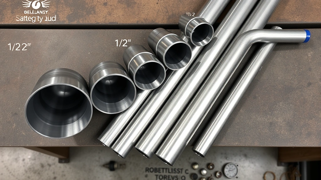
A gas pipe sizing chart is a lookup table that correlates pipe diameter, gas demand (in BTU/hour), pipe length, and pressure drop to determine appropriate sizing. Standard charts are organized with pipe diameters listed vertically (typically 1/2″, 3/4″, 1″, 1.25″, 1.5″, and 2″) and pipe lengths listed horizontally (10 feet, 20 feet, 30 feet, etc.). The intersecting cells show maximum BTU/hour capacity for that diameter-length combination at a specified pressure drop, usually 0.3 inches of water column.
To use a chart effectively: first, calculate your total gas demand in BTU/hour by summing all appliances with appropriate demand factors. Second, measure the actual pipe length from the supply source to the furthest appliance on that branch. Third, locate the row matching your calculated demand and the column matching your pipe length. The smallest pipe diameter whose capacity exceeds your demand is your answer. If no single diameter works, you may need to split the load between multiple branches or increase inlet pressure.
Multiple sizing charts exist for different scenarios—natural gas at various inlet pressures, propane at different pressures, and variations for different materials. Always verify you’re using the correct chart for your specific gas type, pressure, and piping material. Manufacturers and code authorities provide standardized charts; using the wrong chart introduces serious safety risks by undersizing pipes.
Professional builders often maintain digital versions of gas pipe sizing charts integrated into their design software, allowing rapid calculations during project planning. However, understanding the underlying principles—how pipe diameter, length, and pressure drop interact—remains essential for recognizing when results seem unreasonable and catching calculation errors.
Pressure Drop Calculations Explained
Pressure drop quantifies how much pressure is lost as gas travels through pipes due to friction. It’s measured in inches of water column (in. WC), where 1 inch of water column equals 0.036 psi. As gas flows through a pipe, friction between the gas and pipe interior walls removes energy, reducing downstream pressure. This calculation involves several variables that engineers combine using complex formulas or simplified charts.
The fundamental relationship shows that pressure drop increases dramatically with pipe length and flow rate, but decreases with larger pipe diameters. Doubling the pipe diameter reduces pressure drop by a factor of approximately 16—a powerful incentive toward proper sizing. Conversely, doubling the flow rate increases pressure drop by a factor of four, demonstrating why demand calculations must be accurate.
Building codes establish maximum allowable pressure drops to ensure adequate pressure reaches appliances. Most codes limit total pressure drop from the meter to the appliance to 0.3 inches of water column for systems serving multiple appliances, though some jurisdictions allow up to 0.5 in. WC. Individual appliance connections may permit higher drops. Exceeding these limits forces appliances to operate at reduced capacity, consuming more fuel per unit of heat output and increasing emissions.
When calculating pressure drop for complex systems, engineers often use the “longest run method,” sizing the main branch to the furthest appliance, then branching to closer appliances with smaller pipes as needed. This approach simplifies calculations while ensuring adequate pressure throughout the system. Alternatively, detailed hydraulic calculations track pressure at each point, allowing optimization of complex networks.
Materials and Installation Best Practices
Selecting appropriate piping materials significantly impacts both performance and compliance. Black iron pipe remains the code-approved standard in many jurisdictions, offering proven durability and cost-effectiveness over decades. However, it requires threaded connections, which increases labor costs and creates potential leak points. Copper tubing provides superior corrosion resistance and permits soldered connections with fewer leak risks, though cost exceeds black iron. Corrugated stainless steel tubing (CSST) offers flexibility that reduces fitting requirements, faster installation, and smoother interior surfaces that reduce friction.
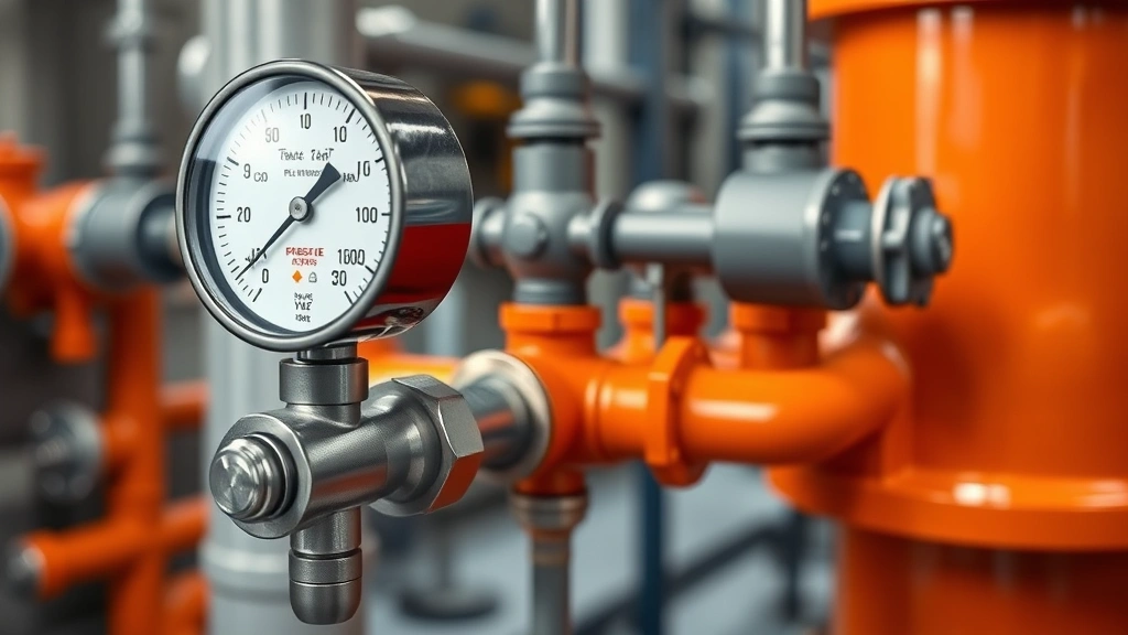
Installation best practices ensure system reliability and safety. All connections must be leak-tested using pressure gauges and soap solution, never flames. Pipes should be securely fastened at regular intervals, typically every 4-6 feet horizontally and every 8 feet vertically, preventing vibration and stress-related failures. Avoid routing gas pipes through walls or concealed spaces unless local codes permit and proper access remains available for inspection and maintenance.
Proper slope is critical for gas systems. Horizontal runs should slope slightly downward (approximately 1/4 inch per 10 feet) toward supply sources to facilitate removal of any condensation. Vertical risers should be sloped back toward the main line. These practices prevent liquid accumulation that could block gas flow or damage regulators and valves.
Consider installing a gas system designed to reduce your environmental footprint by incorporating efficient regulators, properly sized pipes to minimize losses, and quality shut-off valves that enable quick response to leaks. These investments in proper installation infrastructure support both immediate safety and long-term operational efficiency.
Code Compliance and Safety Standards
Gas piping installation is heavily regulated through building codes that vary by jurisdiction but follow consistent principles. The International Fuel Gas Code (IFGC), adopted by most U.S. jurisdictions, establishes comprehensive requirements for gas piping design, materials, installation, testing, and inspection. Builders must verify specific requirements with their local authority having jurisdiction (AHJ) before beginning work.
Code requirements address pipe sizing directly, typically referencing tables or requiring calculations that match the methodology described above. Most codes specify that sizing must accommodate peak demand at the minimum allowable inlet pressure while maintaining minimum pressure at each appliance. Pressure drop limits, material specifications, connection methods, and support requirements all appear in detailed code sections.
Inspection and testing requirements ensure system safety before occupancy. Gas piping must undergo pressure testing at specified pressures (typically 50 psi for up to 30 seconds) to verify no leaks exist. After passing pressure tests, systems are purged of air and tested again with gas at operating pressure. Only qualified inspectors certified by the authority having jurisdiction can approve systems for use.
Professional certification and training matter significantly. Many jurisdictions require that gas piping installation be performed by licensed plumbers or gas fitters who have demonstrated competency through examination. These professionals understand code requirements, calculation methods, and safety protocols that protect building occupants. Attempting installations without proper expertise creates serious safety risks including gas leaks, explosions, and carbon monoxide hazards.
When planning projects, allocate time and budget for proper permitting, inspection, and professional installation. These requirements exist because improper gas piping has caused tragedies. Compliance with codes isn’t bureaucratic obstruction—it’s protection for occupants and surrounding properties.
For builders interested in green technology innovations transforming our future, consider that efficient gas delivery systems represent one aspect of sustainable building. However, also evaluate whether alternatives like electric heating and cooking might better serve your project’s sustainability goals, reducing reliance on fossil fuels entirely.
FAQ
What’s the difference between natural gas and propane pipe sizing?
Propane has a higher specific gravity than natural gas, meaning it’s denser and flows differently through pipes of identical diameter. Propane requires slightly larger pipe diameters than natural gas for equivalent BTU delivery. Always use the correct sizing chart for your specific gas type, as using natural gas charts for propane systems results in undersizing and safety hazards.
Can I use the same pipe size for the entire system?
No. While a single large pipe from the meter could theoretically serve all appliances, this wastes materials and money. Proper design branches to smaller pipes as demand decreases moving away from the supply source. Branch sizing follows the same chart methodology, with each branch sized for its specific demand and length.
What happens if I oversize pipes?
Oversizing wastes material, increases installation costs, and provides no performance benefit. However, it doesn’t create safety hazards like undersizing does. If you’re uncertain about exact demand, slightly oversizing is preferable to undersizing, though proper calculation should eliminate this dilemma.
How often should gas piping be inspected?
Initial inspection occurs before the system is pressurized and again before use. Annual inspections by qualified professionals help identify corrosion, loose connections, or damage. More frequent inspection may be warranted in commercial settings or high-use facilities. Any signs of leaks demand immediate professional attention.
Are there alternatives to gas piping for sustainable buildings?
Yes. Electric heat pumps, induction cooking, and electric water heaters eliminate the need for gas piping entirely, reducing fossil fuel dependence. Visit the SustainWise Hub Blog for comprehensive discussions on sustainable energy solutions that compare gas versus electric options for various building applications.